
4
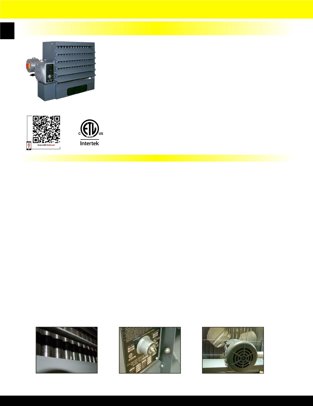
HLA Series Hazardous Location Fan Forced Unit Heater
FAN-FORCED SUSPENDED UNIT HEATERS 3-25 KW FOR T-3B CLASS I, GROUP C & D,
DIVISION 1 & 2 AND CLASS II, GROUPS E, F & G, DIVISIONS 1 & 2.
Shown with optional pilot
light and disconnect switch
Heat Exchanger and Elements:
Heavy walled, painted carbon steel with aluminum fins liquid heat exchanger, liquid filled with three-immersion type copper
sheathed elements. The elements shall have the highest quality nickel-chromium resistance wire encased in a magnesium oxide
dielectric and be hermetically sealed into the heat exchanger core. The heat transfer fluid is Ethylene-glycol solution for operation
to -49 degrees F (– 45 degrees C). Stainless steel and aluminum pressure relief valve for overpressure.
Thermal Cutout High Limit Protection and Optional Pilot Light:
The capillary type manual reset thermal cutout shall be rated for 6000 cycles of service and mounted in the liquid filled heat
exchanger. An optional pilot light to indicate manual reset tripped, if safe operating temperatures are exceeded, is located on
control enclosure.
Motor:
The motor shall be a permanent split capacitor type, permanently lubricated, ball bearing type. The motor shall be rated for
hazardous location and operate at rated voltage of heater, 60 Hz, 1725 RPM.
Control Enclosure:
All controls shall be factory installed and wired in a hazardous location enclosure. Contactors and back-up contactors are heavy
duty type and break all ungrounded conductors and be rated for 100,000 cycles at full load. Standard 24-Volt control circuit shall
be supplied by internal class II transformer. An optional factory wired integral thermostat or standard terminal block for field
wiring to optional remote wall thermostat are wired in control panel. No fan delay relay.
Disconnect Switch:
Factory mounted and wired hazardous location disconnect switch is available as optional accessory.
Cabinet With Adjustable Louvers:
The Cabinet shall be 14 gauge, cold rolled steel with powder coated epoxy finish. Plated fan guards with less than 1/4 inch
spacing to cover motor and fan shall conform to OSHA Requirements.
Note:
Before selecting a hazardous location electric heater refer to Article 500 or other applicable standard referenced in the National
Electric Code.
Product Specifications
• Designed for rugged industrial applications in hazardous locations
where the possibility of explosion or fire exists due to the presence of
certain flammable gases, vapors, powdered metals or dust.
• Permanently sealed, liquid to air, finned tube heat exchanger core.
• Ethylene Glycol to water mixture used as a heat transfer fluid in the
heater core, providing -45° C. (-49° F) freeze damage protection.
• High-performance electric motor driven fan blows air across finned
tubes to effect uniform heat transfer and area heat distribution.
• Manual Reset capillary type limit provides high temperature regulation
and is rated for 6,000 cycles of service.
• Stainless steel and aluminum pressure relief valve for overpressure.
• A back-up contactor is included for additional protection.
• 14 gauge steel cabinet powder coated epoxy paint finish contains heater
core, motor, and fan assembly.
• Narrow gap safety fan guard shields all moving parts.
• Adjustable louvers allow directional control of air.
• Copper conductor wires enclosed in rigid metal conduits carry all
electrical power.
• Box lugs furnished for field connections within approved enclosure.
• Made in U.S.A.
Liquid-to-air heat exchanger
Optional built-in thermostat
Hazardous Location Rated Motor


