


 21 / 129

21
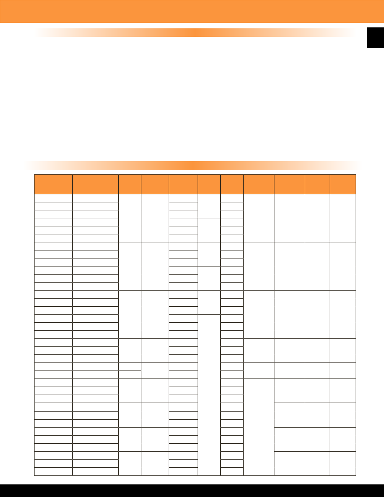
2600 Series Downflow Unit Heater
Standard Models
Product Specifications
SPECIFICATIONS:
The contractor shall furnish and install the 2600 Series electric vertical discharge unit heaters of the size, capacity and
voltage specified. Heaters shall be installed according to the manufacturer’s recommendations and applicable national and local codes.
ELEMENTS:
Elements shall consist of Nickel Chromium alloy resistance wire embedded and completely surrounded in Magnesium Oxide,
enclosed and swagged into corrosion resistant sheaths. Corrosion resistant steel fins shall be permanently attached to the sheaths to provide
maximum heat transfer to the air stream.
MOTORS:
Motors shall be single phase, resilient mounted, totally enclosed, industrial rated with an automatic reset thermal overload protective
device. Motors on heaters up to 20 KW capacity shall be permanently lubricated shaded pole type. Over 20 KW, motors shall be permanent split
capacitor type. Motors shall be mounted out of the main air stream in such a manner as to allow ambient air to be drawn over the motor to reduce
motor temperature. Motor shall be separately removable from beneath the heater without removing the entire heater from mounting bracket.
FAN BLADES:
Fan blades shall be heavy-duty individually balanced axial flow type. Fan speed shall not exceed 1570 RPM.
THERMALOVERLOAD PROTECTION:
All heaters shall be equipped with a manual reset thermal cutout which disconnects elements and
motor in the event normal operating temperatures are exceeded.
WIRING:
Heaters shall be designed for a single supply circuit with elements, motor and control circuits subdivided and fused to conform with
the latest National Electric Code and OSHA requirements. All three phase heaters shall have balanced phases.
CONTROLS:
Heaters shall be controlled by a low voltage wall mounted thermostat. All heaters 25 KW and larger shall be wired for 2 stage
operation. 5 KW through 20 KW units are single stage. All heaters shall be equipped with a fan safety device that causes fan to operate after
elements are de-energized to purge unit of residual heat.
MFG
CATALOG
NUMBER
MFG
MODEL
NUMBER
KW BTU’s
VOLTS PH
AMPS CONTROL
VOLTS
TEMP
RISE
O
F CFM WT
(LBS)
07157502
F1F2605CA1
5
17065
208
1
24.03
24
34
490
75
07157602
H1H2605CA1
240
20.83
07157702
G1G2605CA1
277
18.05
07157802
F3F2605CA1
208
3
13.89
07157902
H3H2605CA1
240
12.04
07158002
P3P2605CA1
480
6.02
07158202
F1F2607CA1
7.5
25598
208
1
36.05
24
45
560
75
07158302
H1H2607CA1
240
31.25
07158402
G1G2607CA1
277
27.07
07158502
F3F2607CA1
208
3
20.84
07158602
H3H2607CA1
240
18.06
07158702
P3P2607CA1
480
9.03
07158902
F1F2610CA1
10
34130
208
1
48.07
24
26
1200
75
07159002
H1H2610CA1
240
41.66
07159102
G1G2610CA1
277
36.1
07159202
F3F2610CA1
208
3
27.79
07159302
H3H2610CA1
240
24.08
07159402
P3P2610CA1
480
12.04
07159602
F3F2615CA1
15
51195
208
41.68
24
39
1200
75
07159702
H3H2615CA1
240
36.12
07159802
P3P2615CA1
480
18.06
07160002
H3H2620CA1 19.4
68260
240
48.16
24
52
1200
75
07160102
P3P2620CA1
20
480
24.08
07175102
F3F2625CA1
25
85325
208
69.48
24
24
3300
175
07175202
H3H2625CA1
240
60.21
07175302
P3P2625CA1
480
30.1
07175502
F3F2630CA1
30 102390
208
83.37
29
3300
175
07175602
H3H2630CA1
240
72.25
07175702
P3P2630CA1
480
36.12
07175902
F3F2640CA1
40 136520
208
111.17
38
3300
175
07176002
H3H2640CA1
240
96.33
07176102
P3P2640CA1
480
48.16
07176302
F3F2650CA1
50 170650
208
138.96
48
3300
175
07176402
H3H2650CA1
240
120.42
07176502
P3P2650CA1
480
60.21